Layout -- Details
OK, so we’ve covered the basic objects, and how they are created, and we’ve covered hierarchical design, view levels and layers. Let’s dig in a bit deeper with some more details....
Use Hierarchy
To the extent reasonably possible, use hierarchy in your design. It often makes both mask-masking and e-beam writing faster, and thus cheaper. For certain more advanced options such as proximity correction, the time/cost savings can be significant. It also makes design modifications much easier, and many times, it’s necessary to do design several iterations of design modifications to get your final desired lithography. Most mask shops specifically request that you do not send them flattened data (that is, data without hierarchy) because it adds too much to their overhead.
Polygons
There are some very important details about polygons of which you should be aware:
Illegal Polygons
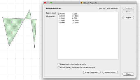
It is possible to create various illegal polygons. Self-intersecting polygons, such as shown here, are not legal in any known mask-making or e-beam system.
Although self-intersection or self-overlapping polygons are illegal, self-touching polygons, in which one or more sides touches another side, but not overlaps, are allowed, and are a way to have “holes” inside of other shapes.
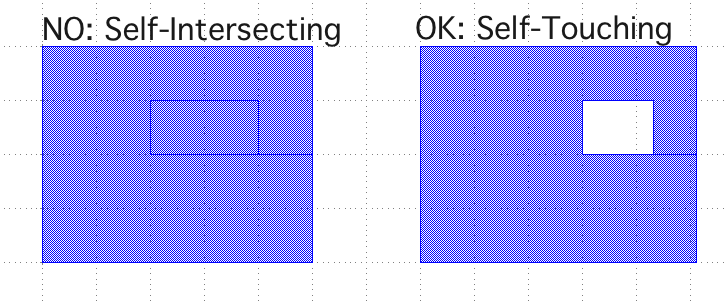
LayoutEditor is, by default, smart about these two illegal polygon types, and will try to detect and repair polygons of this type - See the options in the Preferences/Settings under Shapes : General : Polygon Checks.
Creating Holes In Shapes
A common question, then is how do you create a shape with a “cut out” or hole in it, such as shown on the right above? In LayoutEditor, there are a few different ways.
Consider the large rectangle here, and say I want to have 3 square holes cut through that rectangle, as drawn.
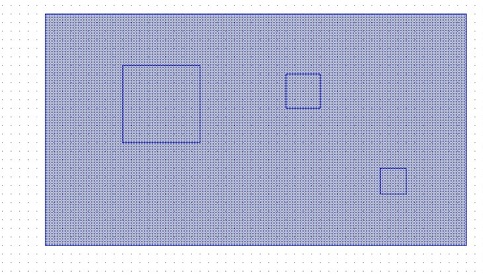
Well, first I select each of the three rectangles, in this case, by making sure I am in "Select" mode by checking the Mouse Help:
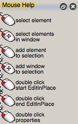
If the top, left-click option is not "Select Element", then get to Select mode by either pressing "Escape", or click toolbar icon "Select/Edit". Then select the three squares, either by Shift-Clicking on each of the three, or by left-dragging a window across the three squares, but not the larger, enclosing rectangle - you don't want that one selected. At this point in this example, there should be exactly 3 boxes (or polygons, depending on how they were created) selected -- you can verify this by looking at the Select Counts in the lower right part of the screen:
Then choose menu item: Utilities : Misc : Punch With Selection.
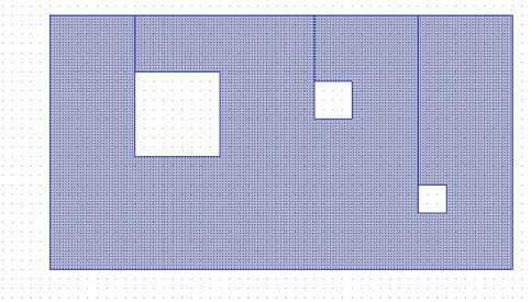
You can also achieve the exact same result with the various Boolean Functions; there is an entire menu of Boolean Tools under the Utilities menu.
Making Curves
As mentioned elsewhere, there really are no curves in the GDS-II data format -- all curves are approximated by polygons. LayoutEditor has a very rich set of options for making curved structures, all of which will be output as polygons when the file is saved. One way to access these shapes is through the Utilities : Circular Tools... menu:
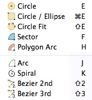
You can make circles, ellipses, arcs, sectors, and Bezier curves. The number of vertices in the curves you create will be controlled by two settings in the Setup/Preferences : Shapes : Defaults : Angle Resolution.
Consider, for example, making very small circles with the JEOL ebeam. You may well be able to use a simple square, which, given electron scattering and resist processing rounding, may come out to be a nice, round dot. If you choose to use 8, or 16 sides for your circle, be aware that the number of shapes the JEOL has to expose goes up quickly:
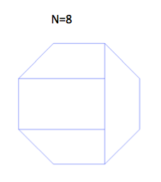
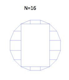
The 8 sided figure requires 4 shapes to expose, while the 16-sided dot has 17 shapes. Why does shape count matter? Well, it directly impacts exposure time, and time is money, so the more sides per shape, the more money your exposure will cost. If you’re making a few dozen or a few hundreds of dots, the difference is completely negligible. But if you want to cover a large area with arrays of closely-spaced dots, the dot count can quickly become enormous -- I’ve written ebeam dots at 2 x 10¹⁰ dots per square centimeter, where shape overhead becomes very significant. For one example, the increment in exposure time from a square to an octagon is about 30% increase in exposure time. For a 16-sided shape, the overhead quickly soars to 340% increase in exposure time -- 3.4 times a long for the same area! The lesson: it pays to consider how many points to make your curves and circles.
Vertex Count in Polygons
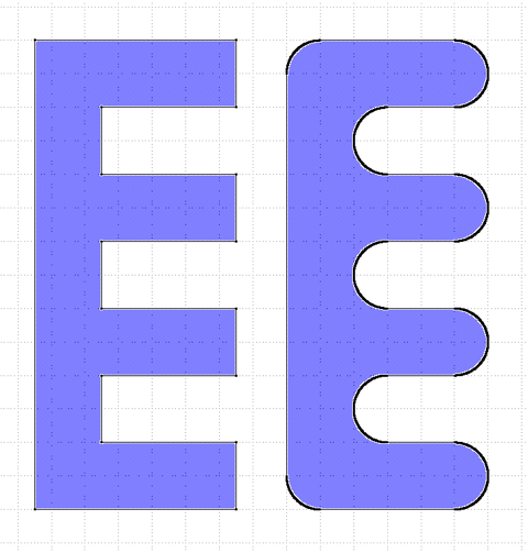
If you’re making curved or complicated polygons, you can get shapes with many, many vertices in each polygon. This has long been a problem-spot with GDS-II data interchange, in particular in research. In integrated circuit manufacturing, by far the largest application of GDS-II, most shapes are simple, orthogonal (sometimes called “Manhattan”) geometries. Anyway, some older software only supports up to 200 vertices per polygon. Other more modern systems support up to 1000 vertices, maybe 2047, in some cases 8192 vertices, and some systems use extensions to allow an arbitrary number of vertices per polygon.
Here are two polygons -- the left one has 16 vertices, the right one has corners rounded off, and has 1440 vertices. This second polygon might create an illegal polygon on some data conversion systems. (One solution is to break this larger polygon into smaller polygons, each of which has fewer vertices.)
Layer Numbers
The upper limit for both layer numbers and datatypes is of some ambiguity with the GDSII data format. The most common range for both Layer numbers and Datatypes 0-255. Very old systems may only support values in the range 0-63, and systems with unofficial extensions often support up to 1023, 2047, or even 8191 layers and/or datatypes in a file. There’s no way to know in advance what values your mask-making or writing system can handle; you’ll have to check before you make your design. Of course, the safest option is just to stay in the range 0-63 for both layer and datatype values; all known systems support values in this range.
Datatypes
You may have noticed that objects you create have an additional value assigned to them called a “Datatype”. The Datatype is an integer, also in the range of 0-255 (or 63 for older versions of GDSII, and sometimes 1023, 2047 or 8191, for extended versions of gdsii.) In general, datatype isn’t used for much, but in e-beam, there’s a very valuable function for this value -- it can be used to identify which shapes should receive different exposure doses during ebeam writing. So if you assign different datatypes to different shapes, you will be able to assign different doses to each of those datatype values in the ebeam’s JDF file, provided you prepare the pattern data taking this desired datatype-to-dose mapping into account, as described here.
Exposable text
As mentioned earlier, the TEXT primitive type is not normally exposed by any mask-making or ebeam tools. To have labeling text appear on a mask or ebeam-written layer, the text must be converted to polygon shapes. LayoutEditor does this either by command, for individual objects, or you can even have it automatically convert text to polygons (although I don't recommend this option, because (a), you can then no longer make labeling-only text, and (b) you can no longer edit the text once it has been converted to polygons.
Grid
By all means, use LayoutEditor's GRID capabilities when you are building your layout. While it’s easy to just click away and draw shapes that are about the size you want, and appear near the locations you want, carelessness with size and placement of your shapes will often result in problems later. You want to consider your design and placement grids from the start of your design, in which case, you need to consider how your masks will be built. If you design to a smaller grid, or place shape vertices off-grid, they will be rounded to the nearest grid point, which might cause problems with your design, by, for example, shifting some shapes or changing the size of some shapes as they snap to the nearest grid point. So what grid should you use? Well, as always, that depends on the capability of your mask making shop or ebeam. PhotoSciences, for example, specifies the use of a 1 um grid for all layouts. CompuGraphics is a considerably more expensive mask shop, and like many mask shops, has a range of grid options available, but indicates rapidly increasing price with smaller grid sizes. The design grids they offer include: 0.125 um (=$), 0.1 um (=$), 0.0625 um (=$$), 0.05 um (=$$$+), 0.03125 um (=$$$$), 0.025 um (=$$$$$). (Yes, the $-signs are their indication of price!). Why so much more expensive? Well, the in general, machine time goes as the inverse square of machine grid, so the time for a 0.025 um grid mask may be up to 25X longer than a 0.125 grid mask, and well, as the saying goes: time is money.For our direct write ebeam, the grid sizes are discussed in detail here. The placement grid is typically 1 nm, while the exposure grid is mostly often some even integer multiple of this value, ranging from 2 nm (medium current HSQ exposures) to 20 (high current maN exposures).
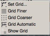
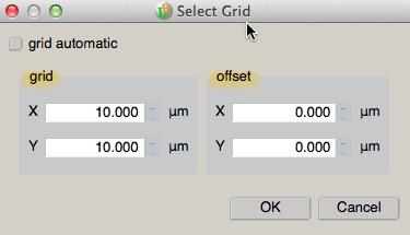
In LayoutEditor, there’s quite a bit of flexibility in how grids are implemented, which means some complexity as well. First you can have the grid displayed or not displayed. Next, you can have the size of the displayed grid change automatically as you zoon, or have it remain fixed, in which case, you can then change the grid to be finer or coarser. Lastly, you can set the grid to be exactly what spacing and offset from the coordinate origin you want. All of these settings are under the Zoom menu, or toolbar icons, or by right-clicking on the grid display at the lower center of the window.
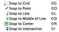
You can also control how the cursor and any coordinates you enter behaves with respect to whatever grid you have defined. This is known as snapping, and you also set this under the Zoom menu, or by Toolbar icons.
Origin
You should also take some care to place your design origin, the (0,0) coordinate, at some sensible location. The two most common locations are the lower left corner, and the center. Placing the origin arbitrarily will complicate your future work, especially when doing layer-to-layer alignment with the e-beam, where you need to specify the location of each alignment mark with respect to the pattern origin. You will typically have to know your data extents for either ebeam exposures or mask making, and it’s just easier and less error prone to report a data extent such as (0,0) to (3200, 4600) rather than (-1542.23, 7253.02) to (1657.77, 11853.02).
Cell Names
Some CAD systems allow more flexibility than others with respect to cell naming. The official GDSII specification says this:
- Cell names can be up to 32 characters in length.
- Legal characters are: A-Z, a-z, 0-9, _ , ?, $
- Do not start names with numbers
I also recommend you avoid having the same cell name in different cases, for example "Top", "TOP", and "top" in the same library. This is very confusing, and some data processing systems do not differentiate well between these names.
Zero-width Paths
In general, shapes must have area to be exposed by a mask-maker or an ebeam system. There is one exception to this with our JEOL e-beam system. We can use a Zero-Width Path, that is, a PATH primitive with a width specified as 0, to generate what e-beam writers refer to as a “Single Pass Line”, which is a single-trace of the electron beam, independent of the grid sized used. Note that while using Single Pass Lines will allow you to theoretically achieve the smallest possible linewidths, some additional overhead and care is necessary, both during pattern preparation, and job file setup, as you must explicitly enable Single Pass Lines in your BEAMER conversion, and you must specify a Line Dose value (in addition to the traditional Area Dose value) in your Job Deck File (JDF).
Non-orthogonal Arrays
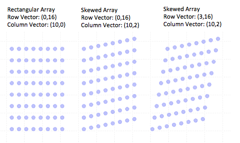
LayoutEditor allows an interesting extension to arrays of cells -- you can specify an arbitrary X,Y vector between each row and column placement. So rather than arrays just being rectangular, they can be offset or skewed. This figure shows the effect of non-zero off-diagonal elements in the array vector specification dialog. This might be a useful feature for your designs. However, this may or may not work with various mask vendors. I can confirm that skewed array placement does work for BEAMER converting files to the JEOL ebeam.
More
Undoubtedly, there are additional design rules and considerations I’m not including here. I’ll try to extend this list as I come up with new issues; let me know if you know of something I’ve omitted here.
If you would like to see more information about CAD layout and good design practices, continue to the Next Page, where I’ve linked to some other sites that have useful information.
